Information on Emissivity and Emissivity Measurement
Content Overview
Table of Contents
Emissivity Testing by Eddy Current
Emissivity testing by eddy current uses the correlation of the emissivity and sheet resistance which is applied by the architectural glass industry since the late 1980s. Here, the silver coating’s ability to transport electrons is used when interacting with incoming visible light. Visible light basically induces an electromagnetic wave, where on atomic scale the electrons are bound to oscillate around a certain orbit, without relevant loss of energy in isolating materials such as glass. Once this electromagnetic wave hits a thin silver layer (e.g. Low Emission), the electrons are able to leave their position and start traveling within the metal film where they quickly lose their energy. Hence, the ability to transport current, correlates with the LowE performance. As sheet resistance measurements using eddy current testing are very easy to apply, this technique is the key technology to characterize emissivity within the glass processing industry. The key benefits of eddy current emissivity testing are:
- Measurement through encapsulation, e.g. silver oxide
- Contact free
- Very robust
- Portable testing options
- High-speed measurement
- High repeatability and accuracy
- Large distances from sensor to substrate enable inline testing of thick and wide glass
- No wearing
Emissivity Measurement Tools
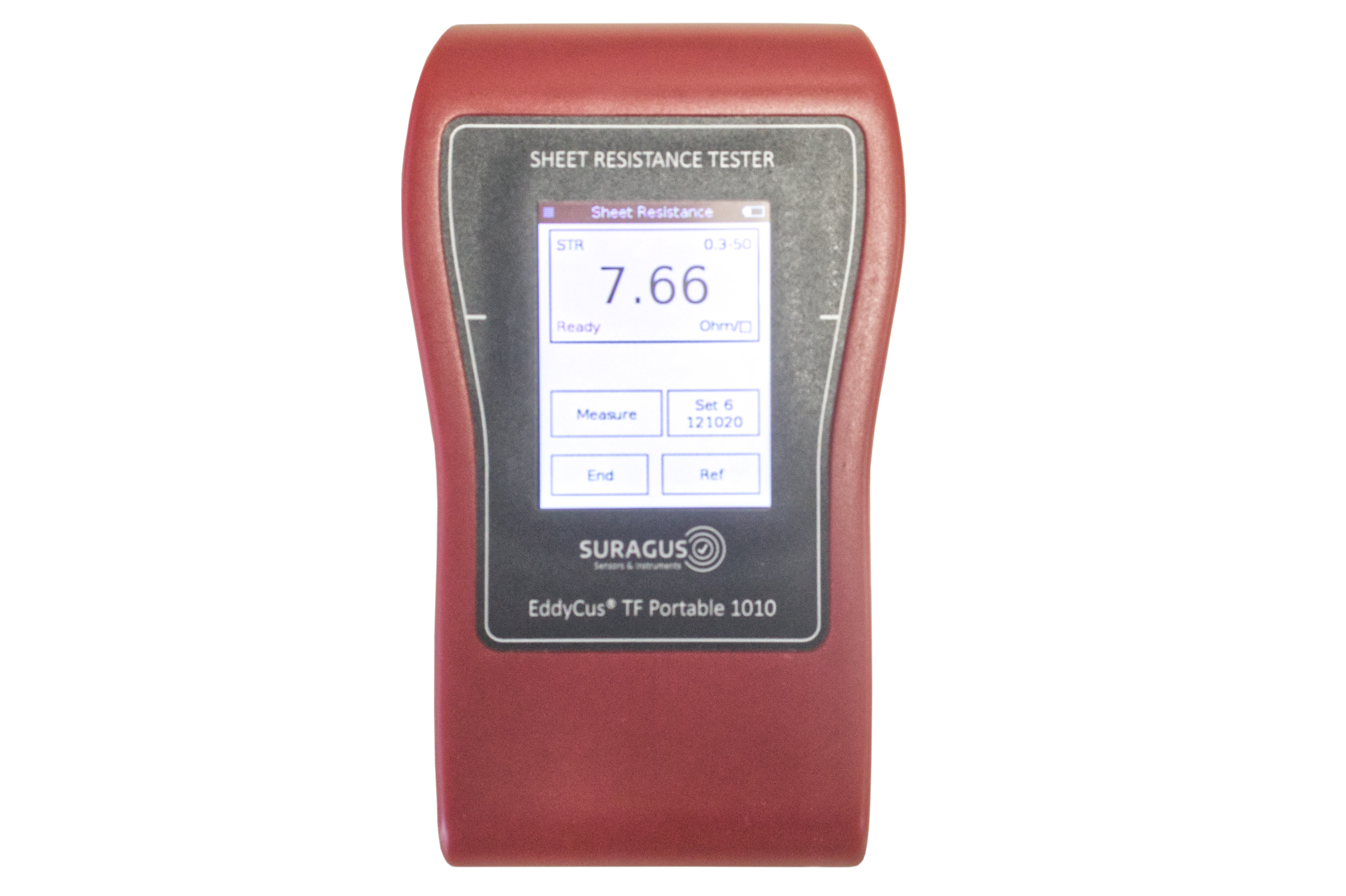
Handheld Devices
for Single Point Measurements
Handheld eddy current devices are designed for fast, random sampling of product quality—commonly used at goods receipt or for inspecting particularly large components after production.
To perform a measurement, the device is placed on the target surface. Press the “Measure” button, and within one second, the result is displayed.
Each measurement provides a precise value at the specific point tested—offering instant, reliable feedback wherever flexibility and speed are essential.
Benchtop Tools
for Single Point Measurements
Our handheld systems are ideal for quick, spot-check measurements—whether at goods receipt, during in-process inspection, or for large-format components where fixed setups are impractical.
Simply place the handheld unit on the surface to be measured, press the “Measure” button, and within one second, the measurement value appears on the display.
Each reading represents the precise value at the measurement point—giving you rapid, reliable feedback wherever you need it.
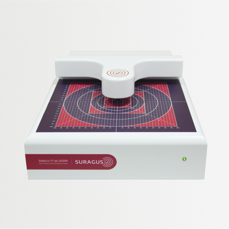
Imaging Tools
for Full Area Images
Our technology delivers highly detailed, full-surface information about product quality—enabling meaningful conclusions about process quality and stability. This data supports targeted optimization of both the manufacturing process (e.g., resource efficiency, throughput speed) and the product itself (e.g., improved homogeneity, compliance with minimum specifications).
For measurement, the sample is placed centrally on the measurement field. Prefabricated holders—such as those for wafers—ensure precise, centered positioning. Simply insert the sample, close the flap, and press “Start Measurement.”
The result: a high-resolution false-color map of the entire layer, generated from thousands of individual measurement points. This visualization gives you actionable insights at a glance.
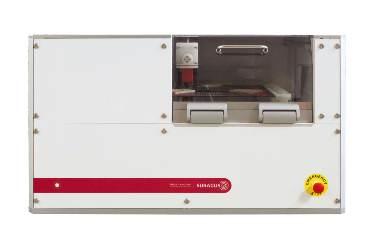
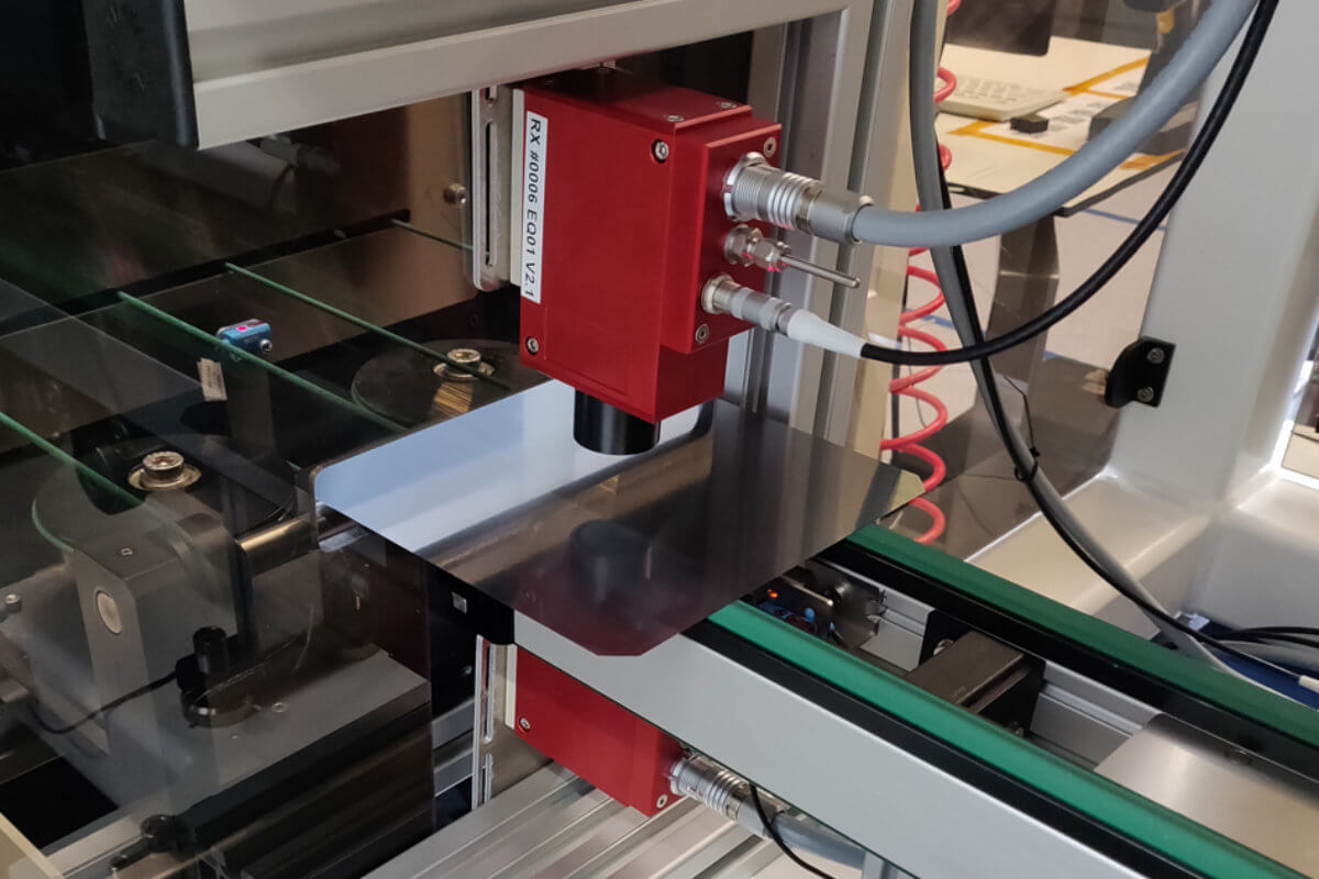
Inline Systems
for Continuous Single Point Measurements
Our inline systems enable continuous acquisition of data on both process quality and product characteristics—before, during, or after a production step. This real-time monitoring is a foundation for production automation, which relies on precise and reliable sensor data.
The system is seamlessly integrated into your existing production line. Once the operator initiates measurement, all data is automatically recorded and stored in a centralized database.
Depending on the system configuration, the output includes one or more line profiles—either centered or positioned at critical points across the layer—providing clear insight into quality trends and process stability in real time.
Characteristics of Optical Coatings
Optical coatings may require thin films that increase the reflection (R) of significant parts of the infrared (IR) wavelengths, such as Solar Control and Low Emissivity (LowE) applications for architectural glass and its retrofit. These are typically hard (pyrolytic) and soft (PVD or MSVD) coated Ag thin films, in addition to seed and oxide layers. The trend towards de-carbonization requires higher performance from high-solar-gain LowE to low-solar-gain LowE. This can be achieved by single, double and triple silver LowE, applied into dual pane integrated glass unit (IGU) or triple pane IGU on position 2, position 4 or position 6. Finally, LowE coating performance is being described by U value (heat transmission coefficient), the solar heat gain coefficient (SHGC), its visible light transmittance (VLT) and the ratio of light to solar gain.
Correlation of Sheet Resistance to Emissivity
The propagation of electromagnetic waves in matter is described by the MAXWELL equations. The values of transmittance, reflectance and absorptance can be derived from the solutions to these equations. The interaction of the visible light with the layers was very well investigated among industry and science and simplifications for the set of equations have been made and evaluated. MAXWELL equations for the absorptance with consideration of KIRCHHOFF’S Law (emissivity ε = absorptance α) result to εn = αn,IR = 4·R□/zo where R□ is the sheet resistance of the layer and zo = 377 Ω is the wave resistance in vacuum. This results to εn = (4 / 377 Ω) · R□ and is typically written as εn = 0.01061·R□. The industry adds typically some “safety markup” when applying this formula for QA and process control. Often this formula is used e = 0.0108 Rsq. You can calculate the emissivity sheet resistance correlation with our emissivity calculator by choosing emissivity as parameter.
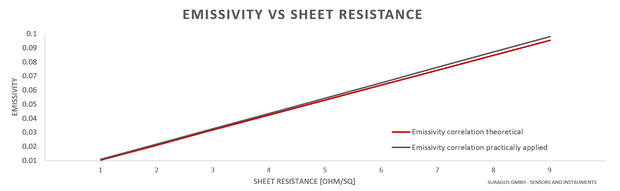
Theoretical correlation: εn = 0.01061·R□ AND practical correlation: εn = 0.0108·R□
Correlation of Sheet Resistance to Thickness
Numerical calculations show that for Ag layers in the thickness range from 5 nm to 20 nm the emissivity Ԑ does not depend explicitly on the film thickness. For further information, please refer to J. Szczerbowski and A. Dietrich, Evaluation and control of the optical and thermal properties of low-emissivity coatings, SPIE Vol 302 (1988).
Testing Devices for Emissivity Measurements
Industry and R&D laboratories have different requirements according to number of measurement samples per day, measurement point density and automation level. In result, four key testing types are commonly applied
- Handheld portable emissivity testing
- Laboratory / Benchtop
- Single point
- Imaging
- Inline / Tool integrated
- Inline static measurement with fixed sensors integrated into conveyer / transportation system
- In-vacuo after each silver deposition (typically 3 monitoring lanes)
- Ex-vacuo (typically 5 monitoring lanes)
- Inline transversing eddy current sensor (typically combined with Zeiss spectrometer)
- Robot / tool integration (e.g. for automotive glass testing, layer removal)
- Inline static measurement with fixed sensors integrated into conveyer / transportation system
Besides typical quality assessment (QA) aspects, high quality glass processing companies require short ramp up times and fast failure and defect detection. The control of the homogeneity of deposition and tempering processes and the reduction of down time facilitates an increase of quality and productivity in architectural glass, automotive glass (e.g. windshields) and transportation glass applications. The solutions address requirements of equipment manufacturers for coatings, equipment manufacturers for tempering process and of the glass processing industry.