Non-contact Eddy Current
Mapping Integration Kit for
Sheet Resistance, Film Thickness
and Resistivity Imaging
Modular Sensor mapping integration kit to generate metal thinfilm thickness, sheet resistance or resistivity images of wafers, pucks and boules
- High resolution images with up to 70,000 measurement points (300 mm @ 1 mm pitch)
- Up to 40 wafers per hour
- Measurement up to the edge of the sample
- 2 – 12 inch wafers
Introduction
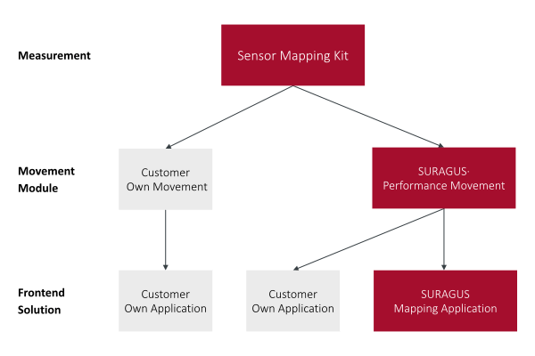
The EddyCus® map IK is a mapping integration kit that consists of three modules. At its core is the sensor kit with sensors, measurement electronics and control unit. Depending on customer requirements the system can be configured for transmission mode with one sensor above and one sensor below the sample, or reflection mode with a single sensor placed either above or below. On request the sensor kit can be integrated into an existing motion system or combined with a dedicated motion solution from SURAGUS. When a SURAGUS solution is used a ready to use software module is available that already includes advanced measurement and recipe management as well as predefined motion control. As an alternative customers can develop their own software. Motion control is then handled via an OPC UA interface for PLC systems and the measurement electronics are accessed through a REST API. The following modules are available
- Base module – Sensor mapping kit
- Motion module
- Existing customer motion system
- SURAGUS performance movement
- Software module
- Customer specific integration throughout SURAGUS MAP Core
- SURAGUS MAP application
High frequency eddy current mapping solutions for contact free measurement of sheet resistance, resistivity and conductivity. Choose the integration level that best fits your application.
Add Your Tooltip Text Here
MAP IK Sensor Mapping Kit Only
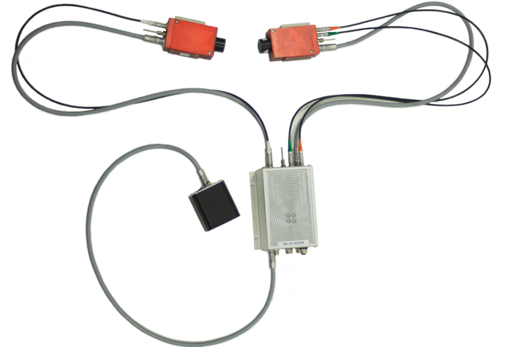
The EddyCus® map IK Sensor Mapping Kit is a sensor only kit without any motion hardware. It is based on contact free eddy current sensors, which are ideally suited for characterizing conductive layers and substrates. This includes:
- Sheet resistance from 0.05 mOhm/sq to 300,000 Ohm/sq
- Thickness of conductive layers from 1 nm to 100 µm
- Resistivity from 0.1 to 1000 mOhm cm
Depending on your requirements three configurations are available
- Transmission mode with a sensor gap up to 25 mm
- Reflection mode
- Top sensor configuration, especially suitable for boules
- Bottom sensor configuration, especially suitable for pucks
The sensors can be integrated into your existing mapping system using various mounting options. STEP data is available on request.
If you do not have a motion platform, you can learn more about our high performance movement platforms in the following section or contact us directly for further options.
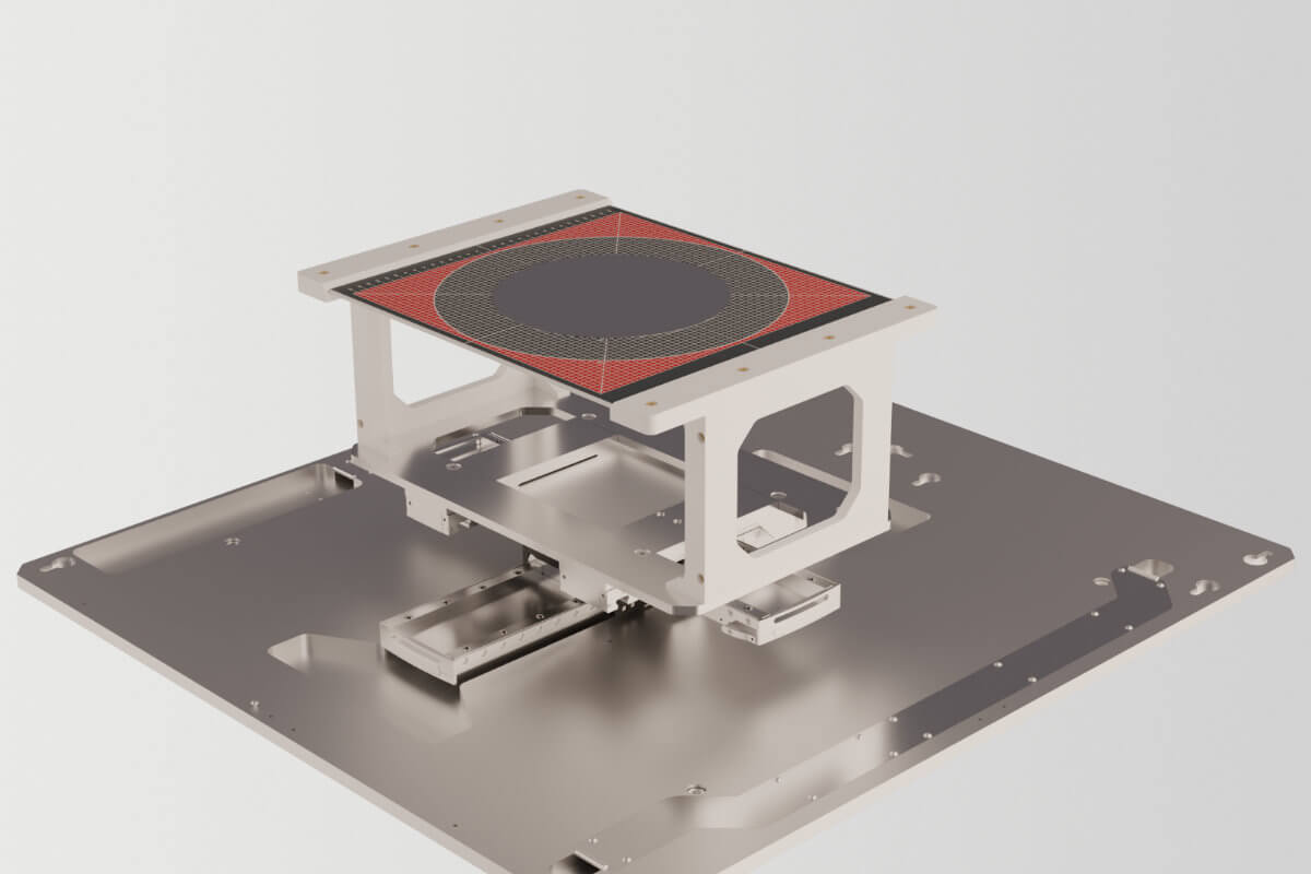
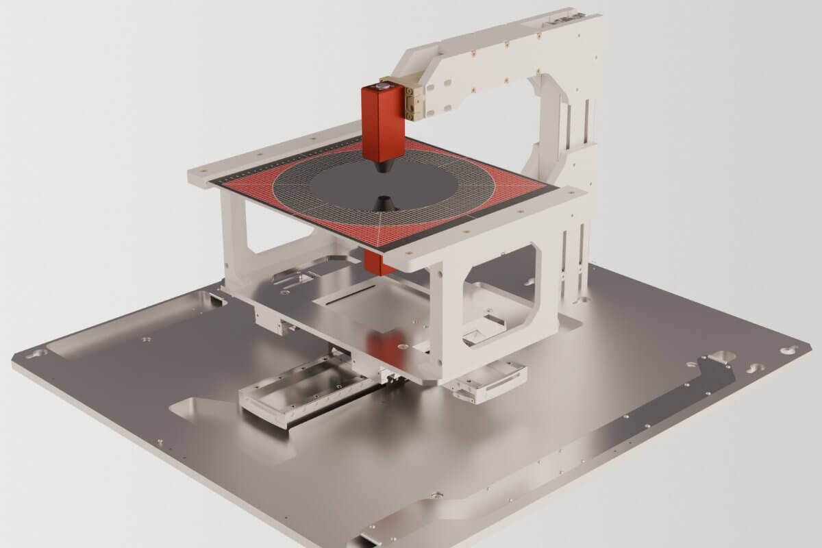
SURAGUS Movement Module
High Performance Movement Module of the Mapping Integration Kit
The high performance mapping platform version is the max-out solution when it comes to speed and measurement performance.
| SURAGUS High Performance Movement | |
| Technology | Linear motors |
| Position Precision Feedback | Very High |
| Edge Exclusion | ≤1 mm |
| Movement Speed | Up to 600 mm/s |
| Initalization Process | Instantly ready to scan (no homing process necessary) |
| Axle Movement | Synchronious movement of x and y axis |
| Scanning Path | Complex but efficient paths are possible (due to synchronious movement) |
| Maintenance | Practically no maintenance (lubrication every 500,000 km) |
| Reflection Mode Accuracy |
±2 % via lift off compensation ±1 % through active piezo distance adaption |
SURAGUS Mapping Integration Software Bundle
SURAGUS Mapping Integration Software Bundle is the central software platform for advanced eddy current mapping. It covers the complete workflow from data acquisition to visualization and makes it easy to integrate SURAGUS systems into existing environments.
- SURAGUS Mapping Integration Software Bundle containing
- SURAGUS MAP Core Driver
- Acquire measurement data from SURAGUS Sensor Mapping Kits
- Process data, for example perform EEC evaluation or derive secondary parameters such as resistivity
- Sufficient to run your own Application
- Optional SURAGUS Mapping Application
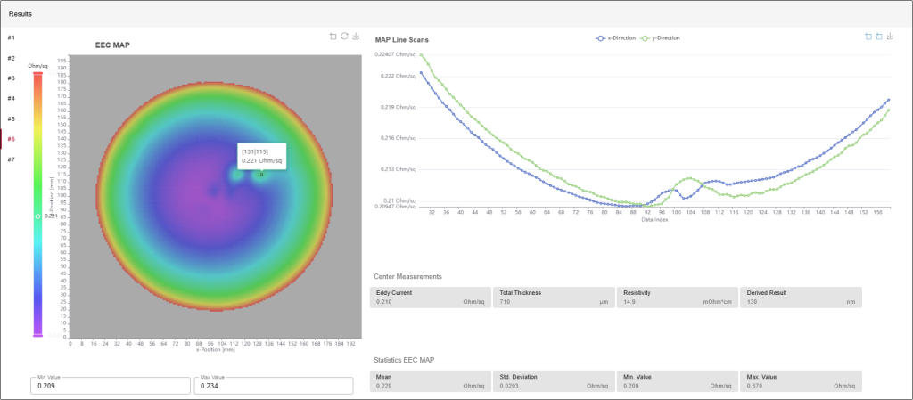
- Visualize measurement results in an intuitive frontend, including detailed maps and statistics
- The application is implemented as modern Python code and is designed to be ready for future extensions. It already supports
- 2D TTV evaluation using KEYENCE confocal sensors
- Integration your own secondary software development kits (SDK)
- For system integration the SURAGUS Mapping Application offers a REST API. This allows higher level systems to trigger measurements, retrieve results and embed SURAGUS data directly into existing process control or quality management solutions.
- SURAGUS MAP Core Driver
Map IK Sensor
Sensor Only Variant-
Eddy Current Sensors
-
Control Unit
-
Wafer, Pucks or Boules
-
REST-API Interface
-
Movement System
-
Complete Frontend Solution
Map IK – Performance
Sensor + Performance Movement-
Eddy Current Sensors
-
Control Unit
-
Wafer, Pucks or Boules
-
REST-API Interface
-
3-Axis Linear Motors
-
Highest Speed (≤ 600 mm/s)
-
Best Edge Exlusion (≤ 1 mm)
-
Smart Scanning Paths
-
Instant Measurement without Homing
-
Complete Frontend Solution
Map IK
Complete Turnkey Solution-
Eddy Current Sensors
-
Control Unit
-
Wafer, Pucks or Boules
-
REST-API Interface
-
3-Axis Linear Motors
-
Highest Speed (≤ 600 mm/s)
-
Best Edge Exlusion (≤ 1 mm)
-
Smart Scanning Paths
-
Instant Measurement without Homing
-
Complete Frontend Solution
Data Table for EddyCus® map IK
Sensor Mapping Kit – Measurement Capabilities
| Transmission mode sensor setup | |
|---|---|
| Sheet resistance measurement range | 0.05 mOhm/sq – 300,000 Ohm/sq | Reflection mode sensor setup |
| Resistivity measurement range | 0.1 – 1,000 mOhm·cm |
| Conductivity measurement range | 0.01 – 65 MS/m |
| Sheet resistance measurement range | 0.05 – 100 Ohm/sq | General features |
| Calibration package | A variety of sheet resistance or resistivity reference standards are available at SURAGUS |
| Encoder input |
ASU Gen1 case: NO ASU Gen2 case: up to 3x (A/B/Z) via internal Trigger Board |
| TTL | ASU Gen1 case: 2x Trigger count + Reset Edge Mode for PTP-applications Trigger rate up to 3kH |
| Software trigger | Included |
| SURAGUS MAP Core |
Path planing PLC module Rest-API to SURAGUS MAP Core OPC UA or others to PLC SECS GEM (E30) |
Movement Features
| Standard Movement | Performance Movement | |
| Base plate | Stable table with a maximum scanning area of 320 x 320 mm base plate ensures mechanical rigidity, and an integrated electronic board behind the actuators hosts the electronic components An optional third axis enables motion in the z direction. This is particularly useful for RMT versions and is available either as a simple z axis or as a closed loop controlled axis for automatic distance adjustment during reflection mode scans. | |
| Housing | No housing included | |
| Location of electronic components | On e-board behind actors | |
| Measurement IPC | ASU control unit to run optional application front end | |
| Number of axis | Up to 3 third axis enables motion in the z direction. This is particularly useful for RMT versions and is available either as a simple z axis or as a closed loop controlled axis for automatic distance adjustment during reflection mode scans. |
|
| SURAGUS Movement Modules | PLC code included | |
| SURAGUS MAP Core |
OPC UA or others to PLC SECS GEM (E30) |
|
| Secondary measurement methodologies | Customer integrated secondary SDKs | |
| Substrates | Wafer, pucks and boules with 2 inch – 300 mm diameter | |
| Technology | Stepper motors | Linear motors |
| Position Precision Feedback | High | Very High |
| Edge Exclusion | 3 – 5 mm | ≤1 mm |
| Movement Speed | Up to 150 mm/s | Up to 600 mm/s |
| Initalization Process | Homing process for each imaging | Instantly ready to scan (no homing process necessary) |
| Axle Movement | Sequential movement of x and y axis | Synchronious movement of x and y axis |
| Scanning Path | Simple meander mode | Complex but efficient paths are possible (due to synchronious movement) |
| Maintenance | Lubrication once a year | Practically no maintenance (lubrication every 500,000 km) |
| Reflection Mode Accuracy | ±3 % via lift off compensation |
±2 % via lift off compensation ±1 % through active piezo distance adaption |
| Performance Movement | ||
| Base plate | Stable table with a maximum scanning area of 320 x 320 mm base plate ensures mechanical rigidity, and an integrated electronic board behind the actuators hosts the electronic components An optional third axis enables motion in the z direction. This is particularly useful for RMT versions and is available either as a simple z axis or as a closed loop controlled axis for automatic distance adjustment during reflection mode scans. | |
| Housing | No housing included | |
| Location of electronic components | On e-board behind actors | |
| Measurement IPC | ASU control unit to run optional application front end | |
| Number of axis | Up to 3 third axis enables motion in the z direction. This is particularly useful for RMT versions and is available either as a simple z axis or as a closed loop controlled axis for automatic distance adjustment during reflection mode scans. |
|
| SURAGUS Movement Modules | PLC code included | |
| SURAGUS MAP Core |
OPC UA or others to PLC SECS GEM (E30) |
|
| Secondary measurement methodologies | Customer integrated secondary SDKs | |
| Substrates | Wafer, pucks and boules with 2 inch – 300 mm diameter | |
| Technology | Linear motors | |
| Position Precision Feedback | Very High | |
| Edge Exclusion | ≤1 mm | |
| Movement Speed | Up to 600 mm/s | |
| Initalization Process | Instantly ready to scan (no homing process necessary) | |
| Axle Movement | Synchronious movement of x and y axis | |
| Scanning Path | Complex but efficient paths are possible (due to synchronious movement) | |
| Maintenance | Practically no maintenance (lubrication every 500,000 km) | |
| Reflection Mode Accuracy |
±2 % via lift off compensation ±1 % through active piezo distance adaption |
|
SURAGUS Mapping Application Addon
| Compatible with | SURAGUS Performance Movement Module |
| Measurement acquisition | Included |
| Data processing |
Edge effect compensation algorythm (EEC) included Derive other measures like resistivity |
| Display data | Front end |
Request a Quote
You can use the formular to write us a message.
Frequently Asked Questions
Sheet resistance, metal layer thickness, resistivity
2 inch up to 300 mm wafers via standard adapters